Routing in IP networks
Contents
Routing in IP networks
In a large IP network such as the global Internet, routers need to exchange routing information. The Internet is an interconnection of networks, often called domains, that are under different responsibilities. As of this writing, the Internet is composed on more than 40,000 different domains and this number is still growing 1. A domain can be a small enterprise that manages a few routers in a single building, a larger enterprise with a hundred routers at multiple locations, or a large Internet Service Provider managing thousands of routers. Two classes of routing protocols are used to allow these domains to efficiently exchange routing information.
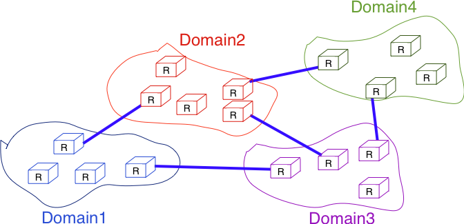
Organization of a small Internet
The first class of routing protocols are the intradomain routing protocols (sometimes also called the interior gateway protocols or IGP). An intradomain routing protocol is used by all routers inside a domain to exchange routing information about the destinations that are reachable inside the domain. There are several intradomain routing protocols. Some domains use RIP, which is a distance vector protocol. Other domains use link-state routing protocols such as OSPF or IS-IS. Finally, some domains use static routing or proprietary protocols such as IGRP or EIGRP.
These intradomain routing protocols usually have two objectives. First, they distribute routing information that corresponds to the shortest path between two routers in the domain. Second, they should allow the routers to quickly recover from link and router failures.
The second class of routing protocols are the interdomain routing protocols (sometimes also called the exterior gateway protocols or EGP). The objective of an interdomain routing protocol is to distribute routing information between domains. For scalability reasons, an interdomain routing protocol must distribute aggregated routing information and considers each domain as a black box.
A very important difference between intradomain and interdomain routing are the routing policies that are used by each domain. Inside a single domain, all routers are considered equal, and when several routes are available to reach a given destination prefix, the best route is selected based on technical criteria such as the route with the shortest delay, the route with the minimum number of hops or the route with the highest bandwidth.
When we consider the interconnection of domains that are managed by different organizations, this is no longer true. Each domain implements its own routing policy. A routing policy is composed of three elements : an import filter that specifies which routes can be accepted by a domain, an export filter that specifies which routes can be advertised by a domain and a ranking algorithm that selects the best route when a domain knows several routes towards the same destination prefix. As we will see later, another important difference is that the objective of the interdomain routing protocol is to find the cheapest route towards each destination. There is only one interdomain routing protocol : BGP.
Intradomain routing
In this section, we briefly describe the key features of the two main intradomain unicast routing protocols : RIP and OSPF. The basic principles of distance vector and link-state routing have been presented earlier.
RIP
The Routing Information Protocol (RIP) is the simplest routing protocol that was standardized for the TCP/IP protocol suite. RIP is defined in RFC 2453. Additional information about RIP may be found in [Malkin1999].
RIP routers periodically exchange RIP messages. The format of these messages is shown below. A RIP message is sent inside a UDP segment whose destination port is set to 521. A RIP message contains several fields. The command field indicates whether the RIP message is a request or a response. When a router boots, its routing table is empty and it cannot forward any packet. To speedup the discovery of the network, it can send a request message to the RIP IPv6 multicast address, FF02::9. All RIP routers listen to this multicast address and any router attached to the subnet will reply by sending its own routing table as a sequence of RIP messages. In steady state, routers multicast one of more RIP response messages every 30 seconds. These messages contain the distance vectors that summarize the router’s routing table. The current version of RIP is version 2 defined in RFC 2453 for IPv4 and RFC 2080 for IPv6.

The RIP message format
Each RIP message contains a set of route entries. Each route entry is encoded as a 20 bytes field whose format is shown below. RIP was initially designed to be suitable for different network layer protocols. Some implementations of RIP were used in XNS or IPX networks RFC 2453. The format of the route entries used by RFC 2080 is shown below. Prefix length is the length of the subnet identifier in bits and the metric is encoded as one byte. The maximum metric supported by RIP is 15.

Format of the RIP IPv6 route entries
Note
A note on timers
The first RIP implementations sent their distance vector exactly every 30 seconds. This worked well in most networks, but some researchers noticed that routers were sometimes overloaded because they were processing too many distance vectors at the same time [FJ1994]. They collected packet traces in these networks and found that after some time the routers’ timers became synchronized, i.e. almost all routers were sending their distance vectors at almost the same time. This synchronization of the transmission times of the distance vectors caused an overload on the routers’ CPU but also increased the convergence time of the protocol in some cases. This was mainly due to the fact that all routers set their timers to the same expiration time after having processed the received distance vectors. Sally Floyd and Van Jacobson proposed in [FJ1994] a simple solution to solve this synchronization problem. Instead of advertising their distance vector exactly after 30 seconds, a router should send its next distance vector after a delay chosen randomly in the [15,45] interval RFC 2080. This randomization of the delays prevents the synchronization that occurs with a fixed delay and is now a recommended practice for protocol designers.
OSPF
Link-state routing protocols are used in IP networks. Open Shortest Path First (OSPF), defined in RFC 2328, is the link state routing protocol that has been standardized by the IETF. The last version of OSPF, which supports IPv6, is defined in RFC 5340. OSPF is frequently used in enterprise networks and in some ISP networks. However, ISP networks often use the IS-IS link-state routing protocol [ISO10589] , which was developed for the ISO CLNP protocol but was adapted to be used in IP RFC 1195 networks before the finalization of the standardization of OSPF. A detailed analysis of ISIS and OSPF may be found in [BMO2006] and [Perlman2000]. Additional information about OSPF may be found in [Moy1998].
Compared to the basics of link-state routing protocols that we discussed in section Link state routing, there are some particularities of OSPF that are worth discussing. First, in a large network, flooding the information about all routers and links to thousands of routers or more may be costly as each router needs to store all the information about the entire network. A better approach would be to introduce hierarchical routing. Hierarchical routing divides the network into regions. All the routers inside a region have detailed information about the topology of the region but only learn aggregated information about the topology of the other regions and their interconnections. OSPF supports a restricted variant of hierarchical routing. In OSPF’s terminology, a region is called an area.
OSPF imposes restrictions on how a network can be divided into areas. An area is a set of routers and links that are grouped together. Usually, the topology of an area is chosen so that a packet sent by one router inside the area can reach any other router in the area without leaving the area 2 . An OSPF area contains two types of routers RFC 2328:
Internal router : A router whose directly connected networks belong to the area
Area border routers : A router that is attached to several areas.
For example, the network shown in the figure below has been divided into three areas : area 0, containing routers RA, RB, RC and RD, area 1, containing routers R1, R3, R4, R5 and RA, and area 2 containing R7, R8, R9, R10, RB and RC. OSPF areas are identified by a 32 bit integer, which is sometimes represented as an IP address. Among the OSPF areas, area 0, also called the backbone area, has a special role. The backbone area groups all the area border routers (routers RA, RB and RC in the figure below) and the routers that are directly connected to the backbone routers but do not belong to another area (router RD in the figure below). An important restriction imposed by OSPF is that the path between two routers that belong to two different areas (e.g. R1 and R8 in the figure below) must pass through the backbone area.
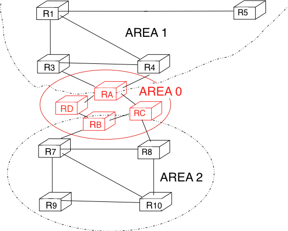
OSPF areas
Inside each non-backbone area, routers distribute the topology of the area by exchanging link state packets with the other routers in the area. The internal routers do not know the topology of other areas, but each router knows how to reach the backbone area. Inside an area, the routers only exchange link-state packets for all destinations that are reachable inside the area. In OSPF, the inter-area routing is done by exchanging distance vectors. This is illustrated by the network topology shown below.
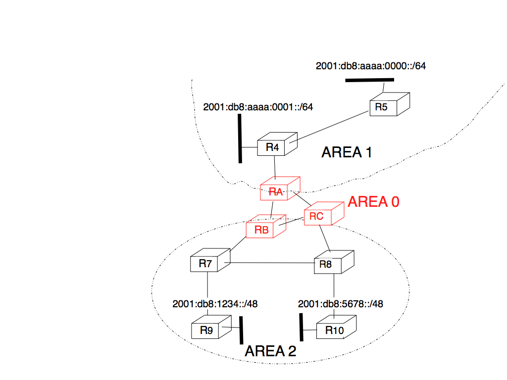
Hierarchical routing with OSPF
Let us first consider OSPF routing inside area 2. All routers in the area learn a route towards 2001:db8:1234::/48 and 2001:db8:5678::/48. The two area border routers, RB and RC, create network summary advertisements. Assuming that all links have a unit link metric, these would be:
RB advertises 2001:db8:1234::/48 at a distance of 2 and 2001:db8:5678::/48 at a distance of 3
RC advertises 2001:db8:5678::/48 at a distance of 2 and 2001:db8:1234::/48 at a distance of 3
These summary advertisements are flooded through the backbone area attached to routers RB and RC. In its routing table, router RA selects the summary advertised by RB to reach 2001:db8:1234::/48 and the summary advertised by RC to reach 2001:db8:5678::/48. Inside area 1, router RA advertises a summary indicating that 2001:db8:1234::/48 and 2001:db8:5678::/48 are both at a distance of 3 from itself.
On the other hand, consider the prefixes 2001:db8:aaaa:0000::/64 and 2001:db8:aaaa:0001::/64 that are inside area 1. Router RA is the only area border router that is attached to this area. This router can create two different network summary advertisements :
2001:db8:aaaa:0001::/64 at a distance of 1 and 2001:db8:aaaa:0000::/64 at a distance of 2 from RA
2001:db8:aaaa:0000::/63 at a distance of 2 from RA
The first summary advertisement provides precise information about the distance used to reach each prefix. However, all routers in the network have to maintain a route towards 2001:db8:aaaa:0000::/64 and a route towards 2001:db8:aaaa:0001::/64 that are both via router RA. The second advertisement would improve the scalability of OSPF by reducing the number of routes that are advertised across area boundaries. However, in practice this requires manual configuration on the border routers.
The second OSPF particularity that is worth discussing is the support of Local Area Networks (LAN). As shown in the example below, several routers may be attached to the same LAN.
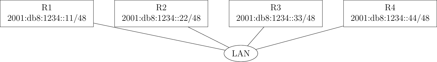
A LAN with routers
A first solution to support such a LAN with a link-state routing protocol would be to consider that a LAN is equivalent to a full-mesh of point-to-point links as if each router can directly reach any other router on the LAN. However, this approach has two important drawbacks :
Each router must exchange HELLOs and link state packets with all the other routers on the LAN. This increases the number of OSPF packets that are sent and processed by each router.
Remote routers, when looking at the topology distributed by OSPF, consider that there is a full-mesh of links between all the LAN routers. Such a full-mesh implies a lot of redundancy in case of failure, while in practice the entire LAN may completely fail. In case of a failure of the entire LAN, all routers need to detect the failures and flood link state packets before the LAN is completely removed from the OSPF topology by remote routers.
To better represent LANs and reduce the number of OSPF packets that are exchanged, OSPF handles LAN differently. When OSPF routers boot on a LAN, they elect 3 one of them as the Designated Router (DR) RFC 2328. The DR router represents the local area network, and advertises the LAN’s subnet. Furthermore, LAN routers only exchange HELLO packets with the DR. Thanks to the utilization of a DR, the topology of the LAN appears as a set of point-to-point links connected to the DR router.
Note
How to quickly detect a link failure ?
Network operators expect an OSPF network to be able to quickly recover from link or router failures [VPD2004]. In an OSPF network, the recovery after a failure is performed in three steps [FFEB2005] :
the routers that are adjacent to the failure detect it quickly. The default solution is to rely on the regular exchange of HELLO packets. However, the interval between successive HELLOs is often set to 10 seconds… Setting the HELLO timer down to a few milliseconds is difficult as HELLO packets are created and processed by the main CPU of the routers and these routers cannot easily generate and process a HELLO packet every millisecond on each of their interfaces. A better solution is to use a dedicated failure detection protocol such as the Bidirectional Forwarding Detection (BFD) protocol defined in [KW2009] that can be implemented directly on the router interfaces. Another solution to be able to detect the failure is to instrument the physical and the datalink layer so that they can interrupt the router when a link fails. Unfortunately, such a solution cannot be used on all types of physical and datalink layers.
the routers that have detected the failure flood their updated link state packets in the network
all routers update their routing table
A last, but operationally important, point needs to be discussed about intradomain routing protocols such as OSPF and IS-IS. Intradomain routing protocols always select the shortest path for each destination. In practice, there are often several equal paths towards the same destination. When a router computes several equal cost paths towards one destination, it can use these paths in different ways.
A first approach is to select one of the equal cost paths (e.g. the first or the last path found by the SPF computation) and install it in the forwarding table. In this case, only one path is used to reach each destination.
A second approach is to install all equal cost paths 4 in the forwarding table and load-balance the packets on the different paths. Consider the case where a router has N different outgoing interfaces to reach destination d. A first possibility to load-balance the traffic among these interfaces is to use round-robin. Round-robin allows equally balancing the packets among the N outgoing interfaces. This equal load-balancing is important in practice because it allows better spreading the load throughout the network. However, few networks use this round-robin strategy to load-balance traffic on routers. The main drawback of round-robin is that packets that belong to the same flow (e.g. TCP connection) may be forwarded over different paths. If packets belonging to the same TCP connection are sent over different paths, they will probably experience different delays and arrive out-of-sequence at their destination. When a TCP receiver detects out-of-order segments, it sends duplicate acknowledgments that may cause the sender to initiate a fast retransmission and enter congestion avoidance. Thus, out-of-order segments may lead to lower TCP performance. This is annoying for a load-balancing technique whose objective is to improve the network performance by spreading the load.
To efficiently spread the load over different paths, routers need to implement per-flow load-balancing. This implies that they must forward all the packets that belong to the same flow on the same path. Since a TCP connection is always identified by the four-tuple (source and destination addresses, source and destination ports), one possibility would be to select an outgoing interface upon arrival of the first packet of the flow and store this decision in the router’s memory. Unfortunately, such a solution does not scale since the required memory grows with the number of TCP connections that pass through the router.
Fortunately, it is possible to perform per-flow load balancing without maintaining any state on the router. Most routers today use hash functions for this purpose RFC 2991. When a packet arrives, the router extracts the Next Header information and the four-tuple from the packet and computes :
\(hash(NextHeader,IP_{src},IP_{dst},Port_{src},Port_{dst}) \pmod{N}\)
In this formula, N is the number of outgoing interfaces on the equal cost paths towards the packet’s destination. Various hash functions are possible, including CRC, checksum or MD5 RFC 2991. Since the hash function is computed over the four-tuple, the same hash value will be computed for all packets belonging to the same flow. This prevents reordering due to load balancing inside the network. Most routers support this kind of load-balancing today [ACO+2006].
Footnotes
- 1
See http://bgp.potaroo.net/index-as.html for reports on the evolution of the number of Autonomous Systems over time.
- 2
OSPF can support virtual links to connect routers together that belong to the same area but are not directly connected. However, this goes beyond this introduction to OSPF.
- 3
The OSPF Designated Router election procedure is defined in RFC 2328. Each router can be configured with a router priority that influences the election process since the router with the highest priority is preferred when an election is run.
- 4
In some networks, there are several dozens of paths towards a given destination. Some routers, due to hardware limitations, cannot install more than 8 or 16 paths in their forwarding table. In this case, a subset of the computed paths is installed in the forwarding table.