The reference models
Contents
The reference models
Given the growing complexity of computer networks, during the 1970s network researchers proposed various reference models to facilitate the description of network protocols and services. Of these, the Open Systems Interconnection (OSI) model [Zimmermann80] was probably the most influential. It served as the basis for the standardization work performed within the ISO to develop global computer network standards. The reference model that we use in this book can be considered as a simplified version of the OSI reference model 1.
The five layers reference model
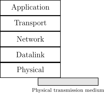
Our reference model is divided into five layers, as shown in the figure below.
The five layers of the reference model
The Physical layer
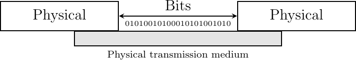
Starting from the bottom, the first layer is the Physical layer. Two communicating devices are linked through a physical medium. This physical medium is used to transfer an electrical or optical signal between two directly connected devices.
An important point to note about the Physical layer is the service that it provides. This service is usually an unreliable service that allows the users of the Physical layer to exchange bits. The unit of information transfer in the Physical layer is the bit. The Physical layer service is unreliable because :
the Physical layer may change, e.g. due to electromagnetic interference, the value of a bit being transmitted
the Physical layer may deliver more bits to the receiver than the bits sent by the sender
the Physical layer may deliver fewer bits to the receiver than the bits sent by the sender
The Physical layer
The Datalink layer
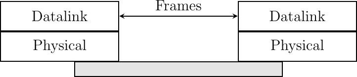
The Datalink layer builds on the service provided by the underlying physical layer. The Datalink layer allows two hosts that are directly connected through the physical layer to exchange information. The unit of information exchanged between two entities in the Datalink layer is a frame. A frame is a finite sequence of bits. Some Datalink layers use variable-length frames while others only use fixed-length frames. Some Datalink layers provide a connection-oriented service while others provide a connectionless service. Some Datalink layers provide reliable delivery while others do not guarantee the correct delivery of the information.
An important point to note about the Datalink layer is that although the figure below indicates that two entities of the Datalink layer exchange frames directly, in reality this is slightly different. When the Datalink layer entity on the left needs to transmit a frame, it issues as many Data.request primitives to the underlying physical layer as there are bits in the frame. The physical layer will then convert the sequence of bits in an electromagnetic or optical signal that will be sent over the physical medium. The physical layer on the right hand side of the figure will decode the received signal, recover the bits and issue the corresponding Data.indication primitives to its Datalink layer entity. If there are no transmission errors, this entity will receive the frame sent earlier.
The Datalink layer
The Network layer
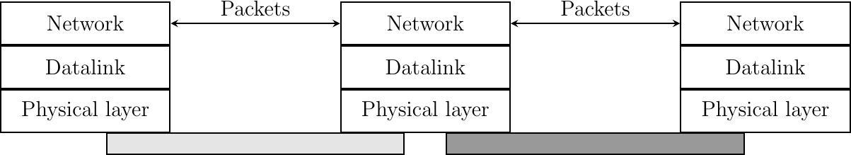
The Datalink layer allows directly connected hosts to exchange information, but it is often necessary to exchange information between hosts that are not attached to the same physical medium. This is the task of the network layer. The network layer is built above the datalink layer. Network layer entities exchange packets. A packet is a finite sequence of bytes that is transported by the datalink layer inside one or more frames. A packet usually contains information about its origin and its destination, and usually passes through several intermediate devices called routers on its way from its origin to its destination.
The network layer
The Transport layer
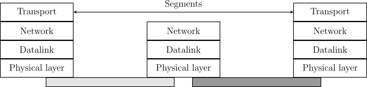
The network layer enables hosts to reach each others. However, different communication flows can take place between the same hosts. These communication flows might have different needs (some require reliable delivery, other not) and need to be distinguished. Ensuring an identification of a communication flow between two given hosts is the task of the transport layer. Transport layer entities exchange segments. A segment is a finite sequence of bytes that are transported inside one or more packets. A transport layer entity issues segments (or sometimes part of segments) as Data.request to the underlying network layer entity.
There are different types of transport layers. The most widely used transport layers on the Internet are TCP, that provides a reliable connection-oriented bytestream transport service, and UDP, that provides an unreliable connection-less transport service.
The transport layer
The Application layer
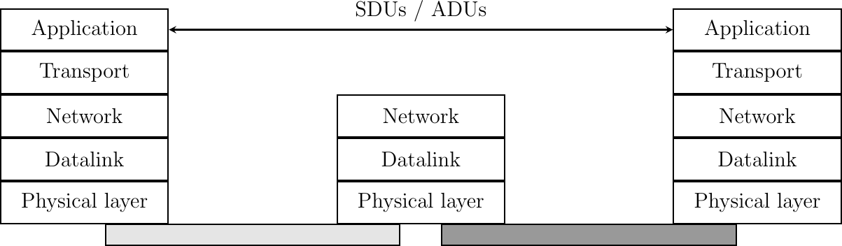
The upper layer of our architecture is the Application layer. This layer includes all the mechanisms and data structures that are necessary for the applications. We will use Application Data Unit (ADU) or the generic Service Data Unit (SDU) term to indicate the data exchanged between two entities of the Application layer.
The Application layer
In the remaining chapters of this text, we will often refer to the information exchanged between entities located in different layers. To avoid any confusion, we will stick to the terminology defined earlier, i.e. :
physical layer entities exchange bits
datalink layer entities exchange frames
network layer entities exchange packets
transport layer entities exchange segments
application layer entities exchange SDUs
Reference models
Two reference models have been successful in the networking community : the OSI reference model and the TCP/IP reference model. We discuss them briefly in this section.
The TCP/IP reference model
In contrast with OSI, the TCP/IP community did not spend a lot of effort defining a detailed reference model; in fact, the goals of the Internet architecture were only documented after TCP/IP had been deployed [Clark88]. RFC 1122, which defines the requirements for Internet hosts, mentions four different layers. Starting from the top, these are :
the Application layer
the Transport layer
the Internet layer which is equivalent to the network layer of our reference model
the Link layer which combines the functions of the physical and datalink layers of our five-layer reference model
Besides this difference in the lower layers, the TCP/IP reference model is very close to the five layers that we use throughout this document.
The OSI reference model
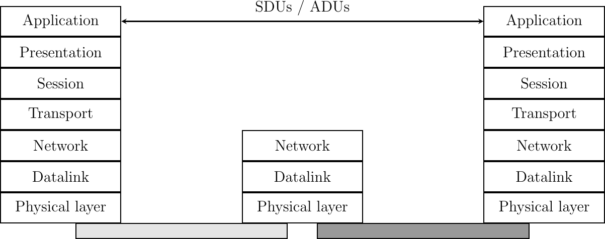
Compared to the five layers reference model explained above, the OSI reference model defined in [X200] is divided in seven layers. The four lower layers are similar to the four lower layers described above. The OSI reference model refined the application layer by dividing it in three layers :
the Session layer. The Session layer contains the protocols and mechanisms that are necessary to organize and to synchronize the dialogue and to manage the data exchange of presentation layer entities. While one of the main functions of the transport layer is to cope with the unreliability of the network layer, the session’s layer objective is to hide the possible failures of transport-level connections to the upper layer higher. For this, the Session Layer provides services that allow establishing a session-connection, to support in-order data exchange (including mechanisms that allow recovering from the abrupt release of an underlying transport connection), and to release the connection in an orderly manner.
the Presentation layer was designed to cope with the different ways of representing information on computers. There are many differences in the way computer store information. Some computers store integers as 32 bits field, others use 64 bits field and the same problem arises with floating point number. For textual information, this is even more complex with the many different character codes that have been used 2. The situation is even more complex when considering the exchange of structured information such as database records. To solve this problem, the Presentation layer provides a common representation of the data transferred. The ASN.1 notation was designed for the Presentation layer and is still used today by some protocols.
the Application layer that contains the mechanisms that do not fit in neither the Presentation nor the Session layer. The OSI Application layer was itself further divided in several generic service elements.
The seven layers of the OSI reference model
Footnotes
- 1
An interesting historical discussion of the OSI-TCP/IP debate may be found in [Russel06]
- 2
There is now a rough consensus for the greater use of the Unicode character format. Unicode can represent more than 100,000 different characters from the known written languages on Earth. Maybe one day, all computers will only use Unicode to represent all their stored characters and Unicode could become the standard format to exchange characters, but we are not yet at this stage today.