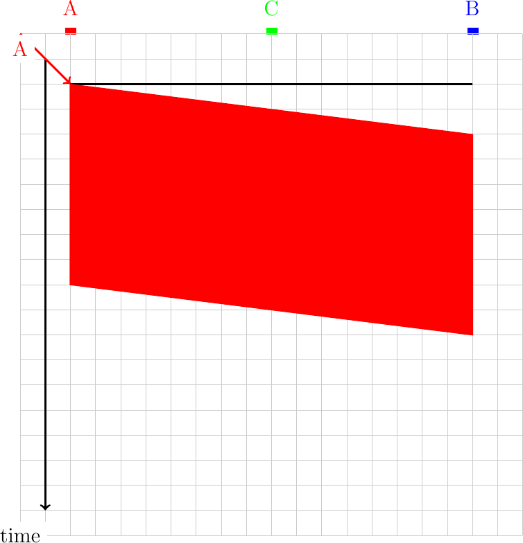
To understand the operation of Medium Access Control algorithms, it is often interesting to use a geometric representation of the transmission of frames on a shared medium. This representation is suitable if the communicating devices are attached to a single cable. Consider a simple scenario with a host connected at one end of a cable. For simplicity, let us consider a cable that has a length of one kilometer. Let us also consider that the propagation delay of the electrical signal is five microseconds per kilometer. The figure below shows the transmission of a 2000 bits frame at 100 Mbps by host A on the cable.
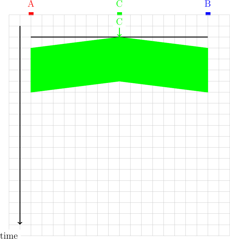
If the transmitting host is located at another position on the shared medium than one of the edges, then the geometrical pattern that represents the transmission of a frame is slightly different. If the transmitting host is placed in the middle of the cable, then the signal is transmitted in both directions on the cable. The figure below shows the transmission of one 100 bits frame at 100 Mbps by host C on the same cable.
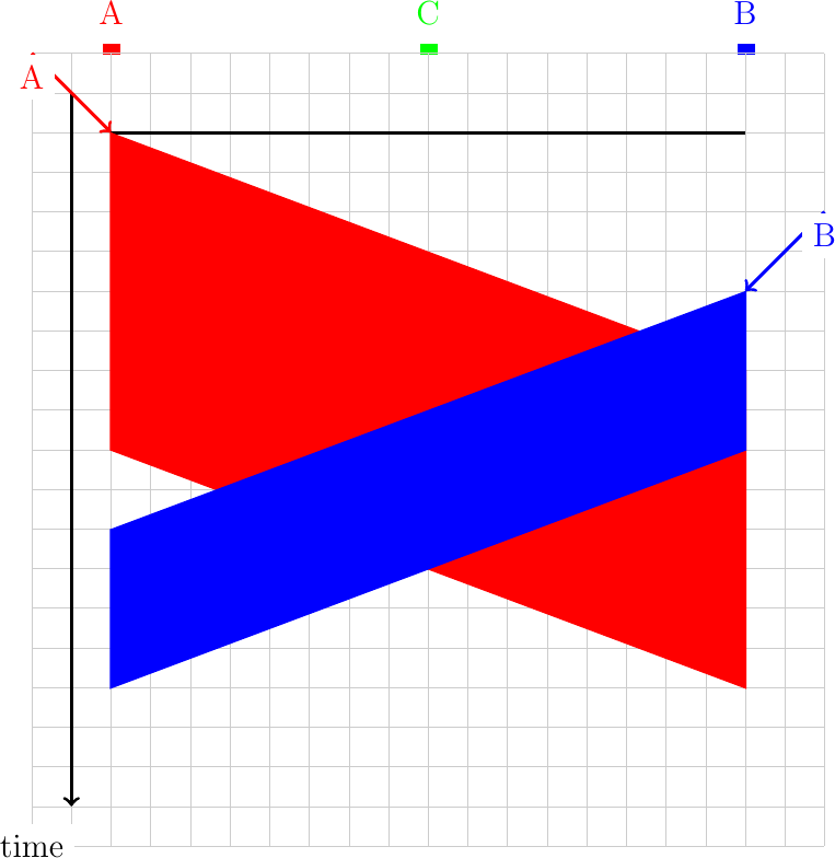
In a shared medium, a collision may happen if two hosts transmit at almost the same time as shown in the example below.
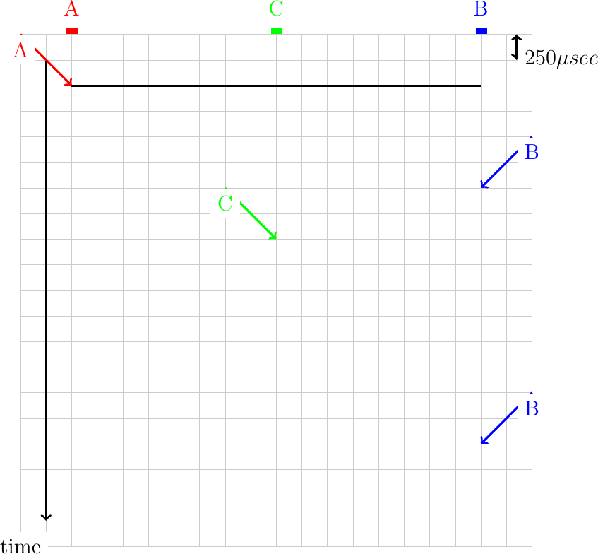
Consider the following scenario for the ALOHA medium access control algorithm. Three hosts are attached to a one-kilometer long cable and transmit 1000 bits frames at 1 Mbps. Each arrow represents a request to transmit a frame on the corresponding host. Each square represents 250 microseconds in the figure. Represent all the transmitted frames and list the frames that collide.
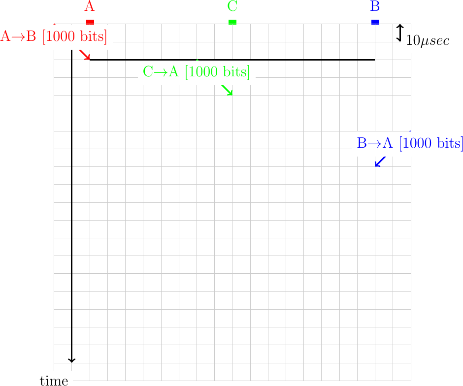
Same question as above, but now consider that the hosts transmit 1000 bits frames at 100 Mbps. The cable has a length of 2 kilometers. C is in the middle of the cable. Each square in the figure below corresponds to 10 microseconds.
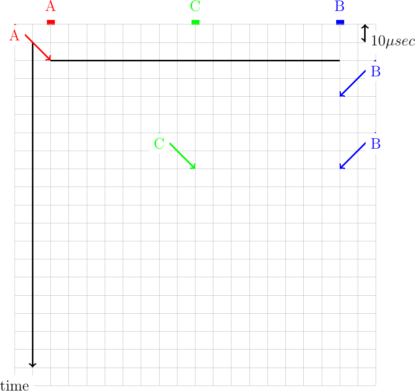
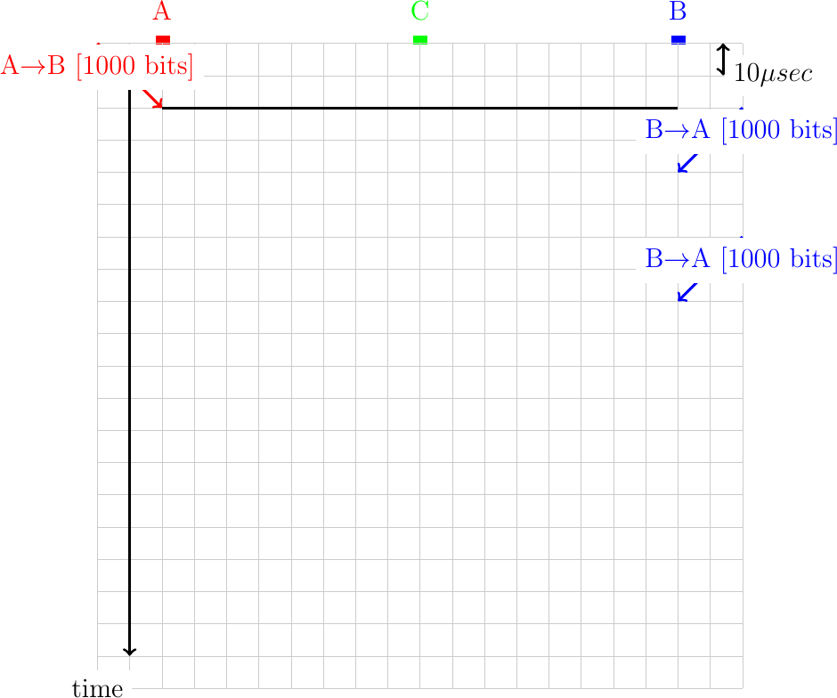
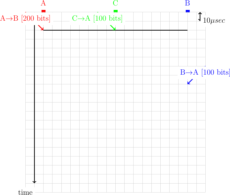
In ALOHA, the hosts rely on acknowledgments to detect whether their frame has been received correctly by the destination. Consider a network running at 100 Mbps where the host exchange 1000 bits frames and acknowledgments of 100 bits. Draw the frames sent by hosts A and B in the figure below. Assume that a square corresponds to 10 microseconds and that the cable has a length of 2 kilometers.
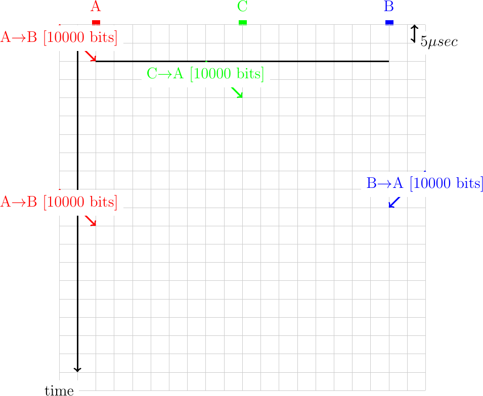
Same question as above, but now assume that the retransmission timer of each host is set to 50 microseconds.
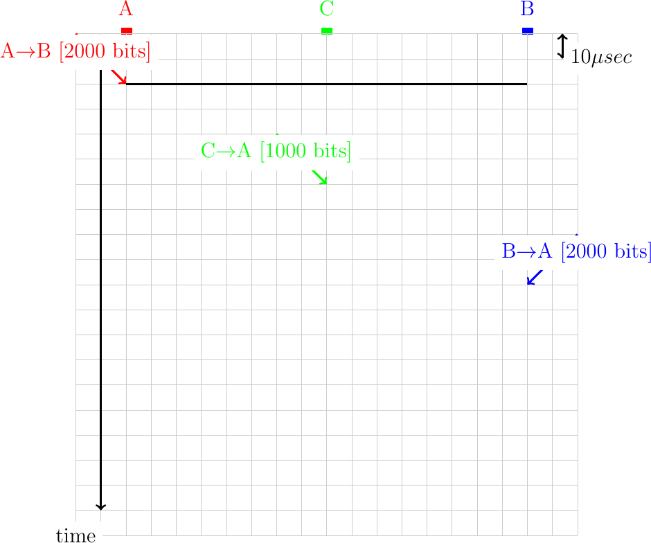
In practice, hosts transmit variable length frames. Consider a cable having a bandwidth of 100 Mbps and a length of 2 kilometers.
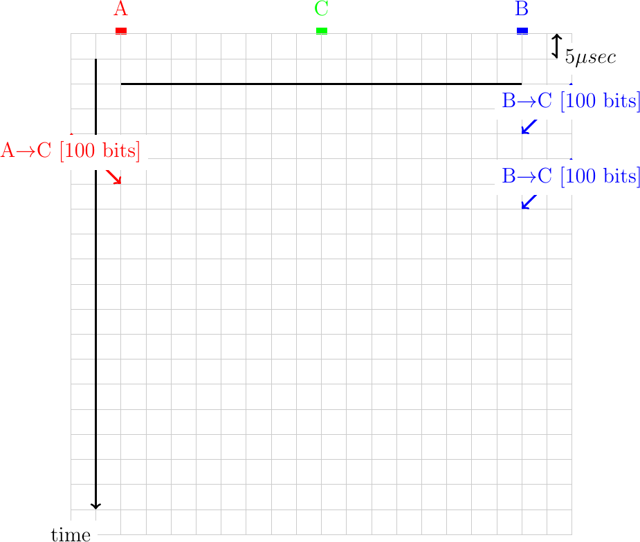
With CSMA, hosts need to listen to the communication channel before starting their transmission. Consider again a 2 kilometers long cable where hosts send frames at 100 Mbps. Show in the figure below the correct transmission of frames with CSMA.
CSMA/CD does not use acknowledgments but instead assumes that each host can detect collisions by listening while transmitting. Consider a 2 kilometers long cable running at 10 Mbps. Show in the figure below the utilization of the communication channel and the collisions that would occur. For this exercise, do not attempt to retransmit the frames that have collided.
Consider again a network that uses CSMA/CD. This time, the bandwidth is set to 1 Gbps and the cable has a length of two kilometers. When a collision occurs, consider that the hosts B and C retransmit immediately while host A waits for the next slot.
An important part of the CSMA/CD algorithm is the exponential backoff. To illustrate the operation of this algorithm, let us consider a cable that has a length of one kilometer. The bandwidth of the network is set to 10 Mbps. Assume that when a collision occurs, host A always selects the highest possible random delay according to the exponential backoff algorithm while host B always selects the shortest one. In this network, the slot time is equal to the time required to transmit 100 bits. We further assume that a host can detect collision immediately (i.e. as soon as the other frame arrives).
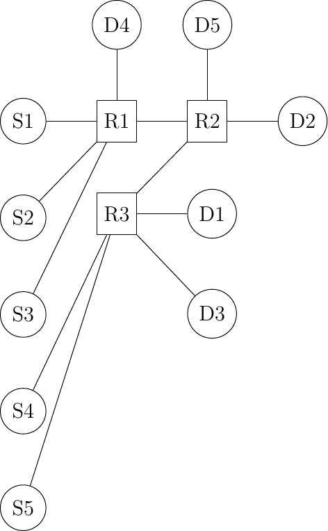
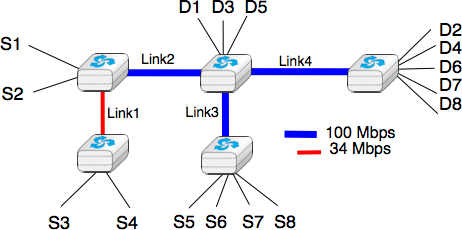
Consider the network below. Compute the max-min fair allocation for the hosts in this network assuming that nodes Sx always send traffic towards node Dx. Furthermore, link R1-R2 has a bandwidth of 10 Mbps while link R2-R3 has a bandwidth of 20 Mbps.
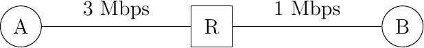
To understand congestion control algorithms, it can also be useful to represent the exchange of packets by using a graphical representation. As a first example, let us consider a very simple network composed of two hosts interconnected through a switch.
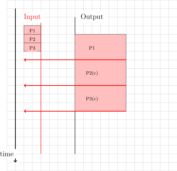
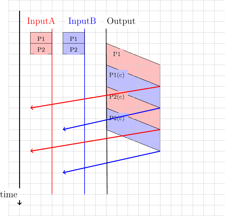
Suppose now that host A uses a window of three segments and sends these three segments immediately. The segments will be queued in the router before being transmitted on the output link and delivered to their destination. The destination will reply with a short acknowledgment segment. A possible visualization of this exchange of packets is represented in the figure below. We assume for this figure that the router marks the packets to indicate congestion as soon as its buffer is non-empty when its receives a packet on its input link. In the figure, a (c) sign is added to each packet to indicate that it has been explicitly marked.
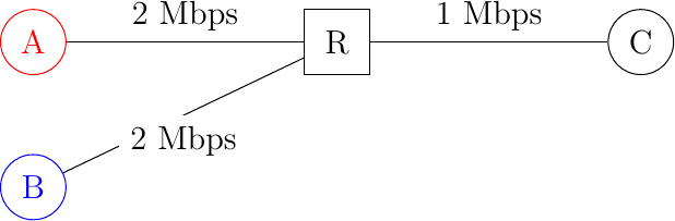
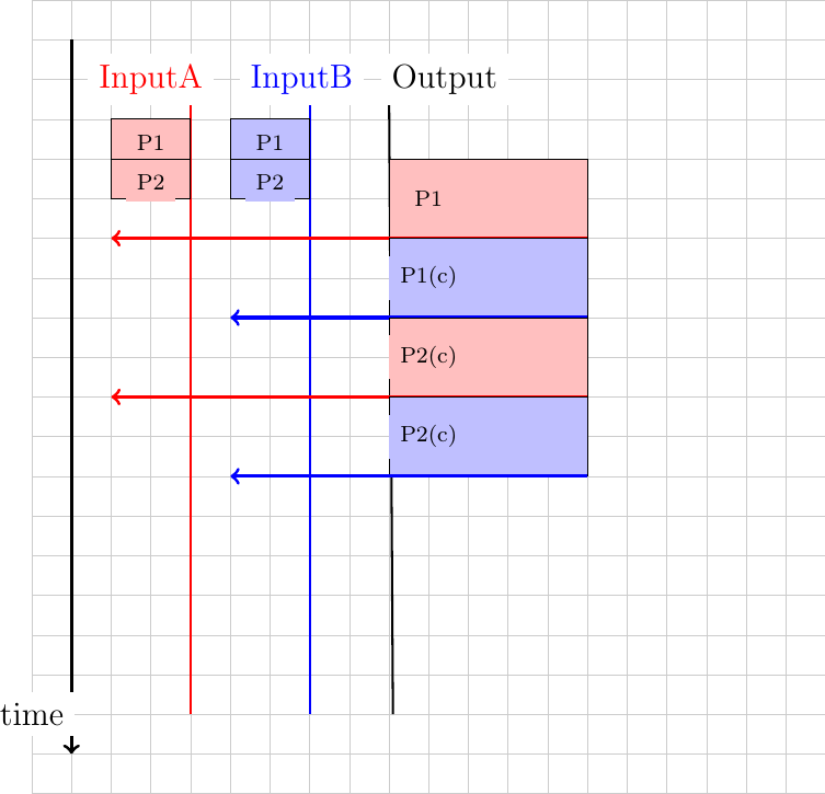
In practice, a router is connected to multiple input links. The figure below shows an example with two hosts.
In general, the links have a non-zero delay. This is illustrated in the figure below where a delay has been added on the link between R and C.
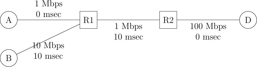
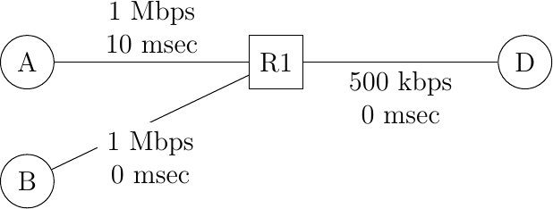
Consider the network depicted in the figure below.
In this network, compute the minimum round-trip-time between A (resp. B) and D. Perform the computation if the hosts send segments containing 1000 bits.
How is the maximum round-trip-time influenced if the buffers of router R1 store 10 packets ?
If hosts A and B send to D 1000 bits segments and use a sending window of four segments, what is the maximum throughput that they can achieve ?
Assume now that R1 is using round-robin scheduling instead of a FIFO buffer. One queue is used to store the packets sent by A and another for the packets sent by B. A sends one 1000 bits packet every second while B sends packets at 10 Mbps. What is the round-trip-time measured by each of these two hosts if each of the two queues of R1 can store 5 packets ?
When analyzing the reaction of a network using round-robin schedulers, it is sometimes useful to consider that the packets sent by each source are equivalent to a fluid and that each scheduler acts as a tap. Using this analogy, consider the network below. In this network, all the links are 100 Mbps and host B is sending packets at 100 Mbps. If A sends at 1, 5, 10, 20, 30, 40, 50, 60, 80 and 100 Mbps, what is the throughput that destination D will receive from A. Use this data to plot a graph that shows the portion of the traffic sent by host A which is received by host D.
Compute the max-min fair bandwidth allocation in the network below.
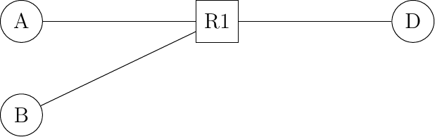
Consider the simple network depicted in the figure below.
In this network, a 250 Kbps link is used between the routers. The propagation delays in the network are negligible. Host A sends 1000 bits long segments so that it takes one msec to transmit one segment on the A-R1 link. Neglecting the transmission delays for the acknowledgments, what is the minimum round-trip time measured on host A with such segments ?
If host A uses a window of two segments and needs to transmit five segments of data. How long does the entire transfer lasts ?
Same question as above, but now host A uses the simple DECBIT congestion control mechanism and a maximum window size of four segments.
Consider the network depicted in the figure below.
Hosts A and B use the simple congestion control scheme described in the book and router R1 uses the DECBIT mechanism to mark packets as soon as its buffers contain one packet. Hosts A and B need to send five segments and start exactly at the same time. How long does each hosts needs to wait to receive the acknowledgment for its fifth segment ?
In a deployed CSMA/CD network, would it be possible to increase or decrease the duration of the slotTime ? Justify your answer
Consider a CSMA/CD network that contains hosts that generate frames at a regular rate. When the transmission rate increases, the amount of collisions increases. For a given network load, measured in bits/sec, would the number of collisions be smaller, equal or larger with short frames than with long frames ?
Slotted ALOHA improves the performance of ALOHA by dividing the time in slots. However, this basic idea raises two interested questions. First how would you enforce the duration of these slots ? Second, should a slot include the time to transmit a data frame or the time to transmit a data frame and the corresponding acknowledgment ?
Like ALOHA, CSMA relies on acknowledgments to detect where a frame has been correctly received. When a host senses an idle channel, if should transmit its frame immediately. How should it react if it detects that another host is already transmitting ? Consider two options :
the host continues to listen until the communication channel becomes free. It transmits as soon as the communication channel becomes free.
the host stops to listen and waits for a random time before sensing again the communication channel to check whether it is free.