IPv6 Networks
Contents
IPv6 Networks
Basic questions on IPv6 Networks
Before starting to determine the paths that packets will follow in an IPv6 network, it is important to remember how to convert IPv6 addresses in binary numbers.
An IPv6 forwarding table contains a list of IPv6 prefixes with their associated nexthop or outgoing interface. When an IPv6 router receives a packet, it forwards it according to its forwarding table. Note that IPv6 routers forward packets along the longest match between the destination address of the packet and the routes in the forwarding table.
Now that you master the basics, you can determine the paths followed by IPv6 packets in simple networks.
Design questions
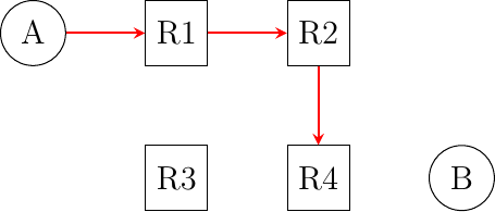
Consider the network shown in the figure below. In this network, the following addresses are used.
host
A:2001:db8:1341:1::Aand its default route points to2001:db8:1341:1::1host
B:2001:db8:1341:4::Band its default route points to2001:db8:1341:4::4
The routers have one address inside each network :
router
R1uses address2001:db8:1341:1::1on its West interface, address2001:db8:1341:12::1on its East interface and address2001:db8:1341:13::1on its South interfacerouter
R2uses address2001:db8:1341:12::2on its West interface, address2001:db8:1341:23::2on its South-West interface and address2001:db8:1341:24::2on its South interface.router
R3uses address2001:db8:1341:34::3on its East interface, address2001:db8:1341:23::3on its North-East interface and address2001:db8:1341:13::3on its North interfacerouter
R4uses address2001:db8:1341:34::4on its West interface, address2001:db8:1341:24::4on its North interface and address2001:db8:1341:4::4on its East interface
The forwarding paths used in a network depend on the forwarding tables installed in the network nodes. Sometimes, these forwarding tables must be configured manually.
In this network, propose the forwarding tables of R2 and R3 that ensure that hosts A and B can exchange packets in both directions.
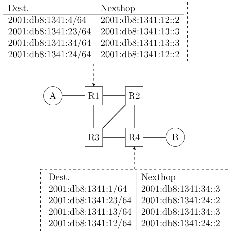
Consider the same network as in the previous question, but now the forwarding tables of
R2andR3are configured as shown below :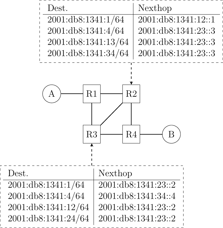
In this network, select all the rules in the shown forwarding tables that ensure that the packets sent from
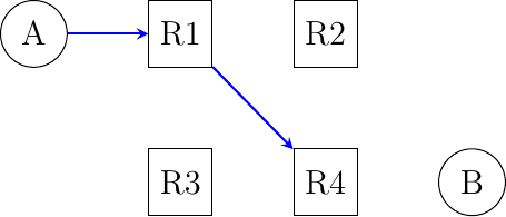
AtoBfollow the reverse path of the packets sent byBtoA.Consider the network shown in the figure below. In this network, the following addresses are used.
host
A:2001:db8:1341:1::Aand its default route points to2001:db8:1341:1::1host
B:2001:db8:1341:4::Band its default route points to2001:db8:1341:4::4
The routers have one address inside each network :
router
R1uses address2001:db8:1341:1::1on its West interface, address2001:db8:1341:12::1on its East interface and address2001:db8:1341:13::1on its South interfacerouter
R2uses address2001:db8:1341:12::2on its West interface, and address2001:db8:1341:24::2on its South interfacerouter
R3uses address2001:db8:1341:34::3on its East interface and address2001:db8:1341:13::3on its North interfacerouter
R4uses address2001:db8:1341:34::4on its West interface, address2001:db8:1341:24::4on its North interface and address2001:db8:1341:4::4on its East interface
Routers R2 and R3 are buggy in this network. Besides the routes for their local interfaces (not shown in the figure), they only have a default route which is shown in the figure below.
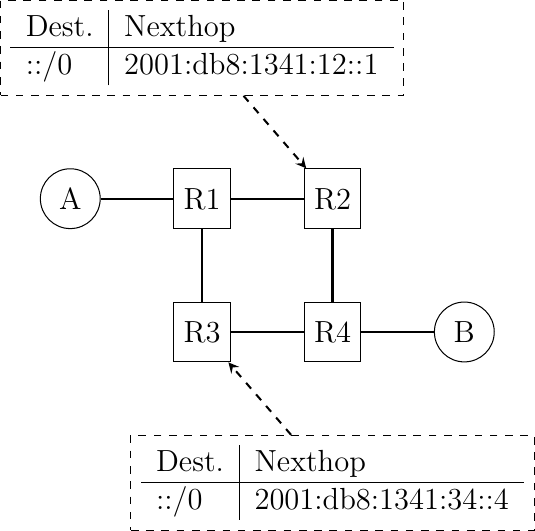
How do you configure the forwarding tables on R1 and R4 so that A can reach B and the reverse ?
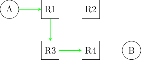
Consider a slightly different network than in the previous question.
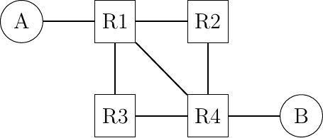
Assuming that the following IPv6 addresses are used :
host
A:2001:db8:1341:1::Aand its default route points to2001:db8:1341:1::1host
B:2001:db8:1341:4::Band its default route points to2001:db8:1341:4::4
The routers have one address inside each network :
router
R1uses address2001:db8:1341:1::1on its West interface, address2001:db8:1341:12::1on its East interface, address2001:db8:1341:14::1on its South-East interface and address2001:db8:1341:13::1on its South interfacerouter
R2uses address2001:db8:1341:12::2on its West interface, and address2001:db8:1341:24::2on its South interfacerouter
R3uses address2001:db8:1341:34::3on its East interface and address2001:db8:1341:13::3on its North interfacerouter
R4uses address2001:db8:1341:34::4on its West interface, address2001:db8:1341:24::4on its North interface, address2001:db8:1341:14::4on its North-West interface and address2001:db8:1341:4::4on its East interfaceCan you configure the forwarding tables so that the following paths are used by packets sent by host
Ato reach one of the four addresses of routerR4?
Do your forwarding tables impose the path used to reach host
Bwhich is attached to routerR4or do you need to configure an additional entry in these tables ?
Consider the network below that contains only routers. This network has been configured by a group of students and you must verify whether the configuration is correct. All the IPv6 addresses are part of the same
/48prefix that we namep. The following subnets are defined in this/48prefix.
p:12/64for the link betweenR1andR2. On this subnet,R1uses addressp:12::1while routerR2uses addressp:12::2
p:13/64for the link betweenR1andR3. On this subnet,R1uses addressp:13::1while routerR3uses addressp:13::3
p:24/64for the link betweenR2andR4. On this subnet,R2uses addressp:24::2while routerR4uses addressp:24::4…
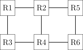
The students have configured the following forwarding tables on these six routers.
on router
R1
on router
R2
on router
R3
on router
R5
on router
R4
on router
R6
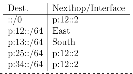
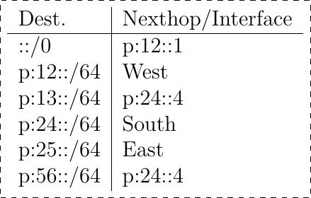
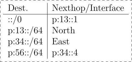
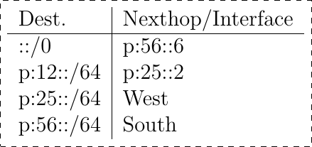
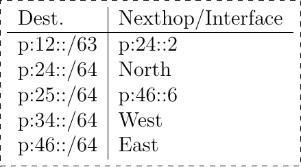
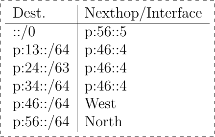
What do you think about the proposed configuration?
Sometimes, static routes must be configured on networks to enforce certain paths. Consider the six routers network shown in the figure below.
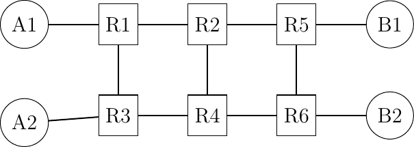
In this network, we will focus on four IPv6 prefixes :
p:0000::/64used on the linkA1-R1.A1uses addressp:0000::A1/64p:0001::/64used on the linkA2-R3.A2uses addressp:0001::A2/64p:0002::/64used on the linkB1-R5.B1uses addressp:0002::B1/64p:0003::/64used on the linkB2-R6.B2uses addressp:0003::B2/64
Can you configure the forwarding tables of the six routers to achieve the following network objectives :
All packets sent by
B1andB2toA1andA2are always forwarded viaR2while all packets fromA1andA2are always forwarded viaR4The packets whose destinations are
A1,A2,B1orB2are never forwarded via routerR4The packets sent by
A1orA2towardsB1are always forwarded viaR2while the packets towardsB2are always forwarded viaR4.
When creating these forwarding tables, try to minimize the number of entries that you install on each router.
When a network is designed, an important element of the design is the IP address allocation plan. A good allocation plan can provide flexibility and help to reduce the size of the forwarding tables.
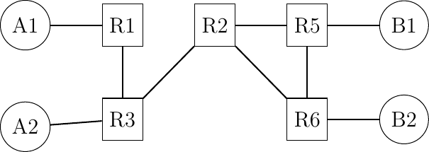
Assign IP subnets to all links in this network so that you can reduce the number of entries in the forwarding tables of all routers. Assume that you have received a
/56prefix that you can use as you want. Each subnet containing a host must be allocated a/64subnet.
Configuring IPv6 Networks
With the previous exercises, you have learned how to reason about IPv6 networks “on paper”. Given the availability of IPv6 implementations, it is also possible to carry out experiments in real and virtual labs. Several virtual environments are possible. In this section, we focus on mininet. mininet is an emulation framework developed at Stanford University that leverages the namespaces features of recent Linux kernels. With those namespaces, a single Linux kernel can support a variety of routers and hosts interconnected by virtual links. mininet has been used by several universities as an educational tool, but unfortunately it was designed without IPv6 support.
During the last years, Olivier Tilmans and Mathieu Jadin have developed the missing piece to enable students to use mininet to experiment with IPv6: ipmininet. ipmininet is a python module that provides the classes that are required to automatically configure IPv6 networks with different routing protocols. It is available from PyPi from https://pypi.org/project/ipmininet/
The syntax of IPMininet is relatively simple and can be learned by looking at a few examples.
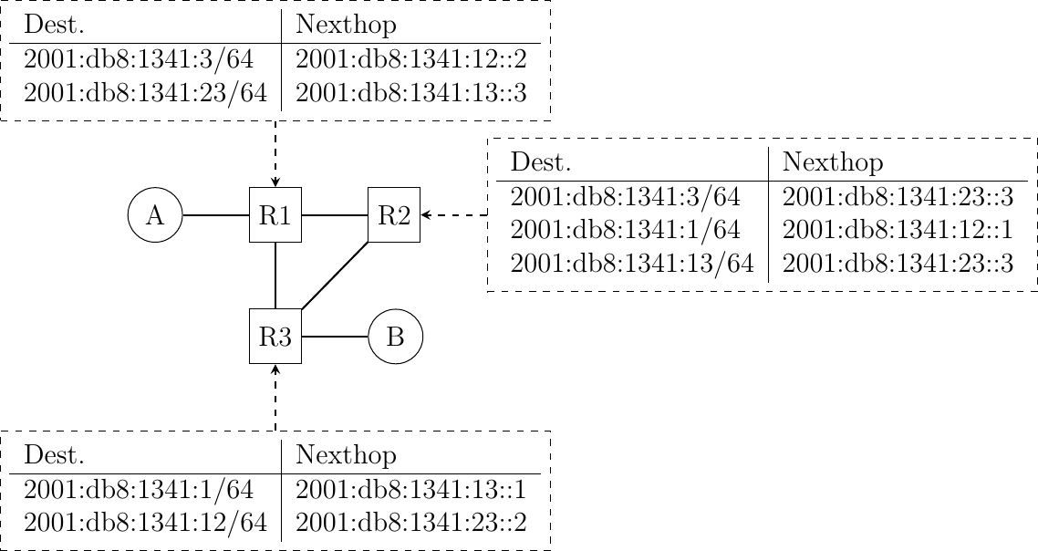
Let us start our exploration of IPv6 routing with a simple network topology that contains two hosts and three routers and uses static routes.
A simple network
IPMininet simplifies the creation of the network topology by providing a simple API. For this, you simply need to declare a class that extends the IPTopo class.
from ipmininet.iptopo import IPTopo
from ipmininet.router.config import RouterConfig, STATIC, StaticRoute
from ipmininet.ipnet import IPNet
from ipmininet.cli import IPCLI

class MyTopology(IPTopo):
    pass
Then, you need to extend the build method that creates routers and hosts.
def build(self, *args, **kwargs):

   # The routers using static routes
   r1 = self.addRouter("r1", config=RouterConfig)
   r2 = self.addRouter("r2", config=RouterConfig)
   r3 = self.addRouter("r3", config=RouterConfig)
   # The hosts
   a = self.addHost("a")
   b = self.addHost("b")
Although IPMininet can assign prefixes and addresses automatically, we use manually assigned addresses in this example.
We use five /64 IPv6 prefixes in this network topology:
2001:db8:1341:1::/64on the link betweenaandr1
2001:db8:1341:12::/64on the link betweenr1andr2
2001:db8:1341:13::/64on the link betweenr1andr3
2001:db8:1341:23::/64on the link betweenr2andr3
2001:db8:1341:1::/64on the link betweenbandr3
We can then manually configure the IPv6 addresses of each host/router on each link. Let us start with the links attached to the two hosts.
# link between r1 and a
lr1a = self.addLink(r1, a)
lr1a[r1].addParams(ip=("2001:db8:1341:1::1/64"))
lr1a[a].addParams(ip=("2001:db8:1341:1::A/64"))
# link between r3 and b
lr3b = self.addLink(r3, b)
lr3b[r3].addParams(ip=("2001:db8:1341:3::3/64"))
lr3b[b].addParams(ip=("2001:db8:1341:3::B/64"))
The same can be done for the three links between the different routers.
lr1r2 = self.addLink(r1, r2)
lr1r2[r1].addParams(ip=("2001:db8:1341:12::1/64"))
lr1r2[r2].addParams(ip=("2001:db8:1341:12::2/64"))

lr1r3 = self.addLink(r1, r3)
lr1r3[r1].addParams(ip=("2001:db8:1341:13::1/64"))
lr1r3[r3].addParams(ip=("2001:db8:1341:13::3/64"))

lr2r3 = self.addLink(r2, r3)
lr2r3[r2].addParams(ip=("2001:db8:1341:23::2/64"))
lr2r3[r3].addParams(ip=("2001:db8:1341:23::3/64"))
With these IP prefixes and the network topology, we can now use IPMininet to create the topology and assign the addresses.
We start by creating the objects that correspond to the static routes on the three routers. The second argument of the addDaemon method is a list of StaticRoute objects. Each of these objects is created by specifying an IP prefix and a nexthop.
# Add static routes
r1.addDaemon(STATIC,
             static_routes=[StaticRoute("2001:db8:1341:3::/64","2001:db8:1341:12::2"),
                            StaticRoute("2001:db8:1341:23::/64","2001:db8:1341:13::3")])

r2.addDaemon(STATIC,
             static_routes=[StaticRoute("2001:db8:1341:3::/64", "2001:db8:1341:23::3"),
                            StaticRoute("2001:db8:1341:1::/64", "2001:db8:1341:12::1"),
                            StaticRoute("2001:db8:1341:13::/64", "2001:db8:1341:23::3")])

r3.addDaemon(STATIC,
             static_routes=[StaticRoute("2001:db8:1341:1::/64", "2001:db8:1341:13::1"),
                            StaticRoute("2001:db8:1341:12::/64","2001:db8:1341:23::2")])
We can now create the hosts and the routers
super(MyTopology, self).build(*args, **kwargs)
With this build method, we can now launch the network by using the python code below.
net = IPNet(topo=MyTopology(), allocate_IPs=False)  # Disable IP auto-allocation
try:
   net.start()
   IPCLI(net)
finally:
   net.stop()
The entire script is available from /exercises/ipmininet_scripts/static-1.py.
To help students to start using IPMininet, Mathieu Jadin has created a Vagrant box that launches a Ubuntu virtual machine with all the required software. See https://ipmininet.readthedocs.io/en/latest/install.html for additional information.
Here is a simple example of the utilization of this Vagrant box.
We start the network topology shown above with the sudo python script.py command. It launches the mininet interactive shell that provides several useful commands:
mininet> help

Documented commands (type help <topic>):
========================================
EOF    gterm  iperf     links   pingall       ports  route   time
dpctl  help   iperfudp  net     pingallfull   px     sh      x
dump   intfs  ips       nodes   pingpair      py     source  xterm
exit   ip     link      noecho  pingpairfull  quit   switch

You may also send a command to a node using:
   <node> command {args}
For example:
   mininet> h1 ifconfig

The interpreter automatically substitutes IP addresses
for node names when a node is the first arg, so commands
like
    mininet> h2 ping h3
should work.

Some character-oriented interactive commands require
noecho:
   mininet> noecho h2 vi foo.py
However, starting up an xterm/gterm is generally better:
   mininet> xterm h2

mininet>
Some of the standard mininet commands assume the utilization of IPv4 and do not have a direct IPv6 equivalent. Here are some useful commands.
The nodes command lists the routers and hosts that have been created in the mininet topology.
mininet> nodes
available nodes are:
a b r1 r2 r3
The links command lists the links that have been instantiated and shows that mapping between the named interfaces on each node.
mininet> links
r1-eth2<->a-eth0 (OK OK)
r1-eth0<->r2-eth0 (OK OK)
r1-eth1<->r3-eth0 (OK OK)
r2-eth1<->r3-eth1 (OK OK)
r3-eth2<->b-eth0 (OK OK)
mininet>
It is possible to execute any of the standard Linux commands to configure the network stack on any of the hosts by prefixing the command with the corresponding host. Remember to always specify inet6 as the address family to retrieve the IPv6 information.
mininet> a ip -f inet6 link
1: lo: <LOOPBACK,UP,LOWER_UP> mtu 65536 qdisc noqueue state UNKNOWN mode DEFAULT group default qlen 1
 link/loopback 00:00:00:00:00:00 brd 00:00:00:00:00:00
2: a-eth0: <BROADCAST,MULTICAST,UP,LOWER_UP> mtu 1500 qdisc noqueue state UP mode DEFAULT group default qlen
 link/ether c6:4e:26:d9:de:6d brd ff:ff:ff:ff:ff:ff link-netnsid 0
Host a has two interfaces: the standard loopback interface and a network interface named a-eth0 that is attached to router r1. We can also verify how the IPv6 addresses have been configured:
mininet> a ip -f inet6 address
1: lo: <LOOPBACK,UP,LOWER_UP> mtu 65536 state UNKNOWN qlen 1
   inet6 ::1/128 scope host
     valid_lft forever preferred_lft forever
2: a-eth0: <BROADCAST,MULTICAST,UP,LOWER_UP> mtu 1500 state UP qlen 1000
   inet6 2001:db8:1341:1::a/64 scope global
     valid_lft forever preferred_lft forever
   inet6 fe80::c44e:26ff:fed9:de6d/64 scope link
     valid_lft forever preferred_lft forever
On its a-eth0 interface, host a uses IPv6 address 2001:db8:1341:1::a/64. The link local address (fe80::c44e:26ff:fed9:de6d/64) will be described in another chapter. Finally, we can check the forwarding table of host a.
mininet> a ip -f inet6 route
2001:db8:1341:1::/64 dev a-eth0  proto kernel  metric 256  pref medium
fe80::/64 dev a-eth0  proto kernel  metric 256  pref medium
default via 2001:db8:1341:1::1 dev a-eth0  metric 1024  pref medium
There are three routes in this table. The first two correspond to the two prefixes that are used over the a-eth0 interface. These routes are automatically created when an IPv6 address is configured on an interface. The last route is the default route (::/0) which points towards 2001:db8:1341:1::1, i.e. router r1.
Another useful command is xterm ‘node’ that allows to launch a terminal on the specified node. This gives you a interactive shell on any node. You can use it to capture packets with tcpdump. As an example, let us use traceroute6(8) to trace the path followed by packets from host a towards the IPv6 address of host b i.e. 2001:db8:1341:3::b. The output of this command shows that the path passes through routers r1, r2 and r3.
mininet> a traceroute6 -q 1 2001:7ab:3::c
traceroute to 2001:7ab:3::c (2001:7ab:3::c) from 2001:7ab:1::a, 30 hops max, 16 byte packets
1  2001:7ab:1::1 (2001:7ab:1::1)  0.105 ms
2  2001:89ab:12::2 (2001:89ab:12::2)  1.131 ms
3  2001:89ab:23::2 (2001:89ab:23::2)  0.845 ms
4  2001:7ab:3::c (2001:7ab:3::c)  0.254 ms
Another interesting mininet command is pingall it allows to check that any host can reach any other host inside the network. It executes a ping from any host to any other host inside the network topology.
mininet> pingall
*** Ping: testing reachability over IPv4 and IPv6
a --IPv6--> b
b --IPv6--> a
*** Results: 0% dropped (2/2 received)
When debugging a network, it can be interesting to capture packets using tcpdump on specific links to check that they follow the expect. If you use tcpdump without any filter, you will capture the packets generated by xterm. To capture packets, you need to specify precise filters that will match the packets of interest. For traceroute6, you need to match the IPv6 packets that contain UDP segments and some ICMPv6 packets. The script below provides a simple filter that you can reuse. It takes one argument: the name of the interface on which tcpdump needs to run.
#!/bin/bash

tcpdump -v -i $1 -n '(ip6 && udp) || (icmp6  && (ip6[40] == 1 || ip6[40]==3))'
Starting from the /exercises/ipmininet_scripts/static-1.py IPMininet script, we can explore classical problems when networks are configured with static routes. A first problem is when a router has an incomplete forwarding table. We configure the static routes as shown below. The entire script is available from /exercises/ipmininet_scripts/static-1-hole.py.
  # Add static routes
  r1.addDaemon(STATIC, static_routes=[StaticRoute("2001:db8:1341:3::/64",
"2001:db8:1341:12::2")])

  r2.addDaemon(STATIC, static_routes=[StaticRoute("2001:db8:1341:1::/64",
"2001:db8:1341:12::1")])

  r3.addDaemon(STATIC, static_routes=[StaticRoute("2001:db8:1341:1::/64",
"2001:db8:1341:13::1")])
We first check with pingall whether the network works correctly.
mininet> pingall
*** Ping: testing reachability over IPv4 and IPv6
a --IPv6--> X
b --IPv6--> X
*** Results: 100% dropped (0/2 received)
The problem can be detected by using traceroute6(8).
mininet> a traceroute6 -q 1 -n 2001:db8:1341:3::b
traceroute to 2001:db8:1341:3::b (2001:db8:1341:3::b) from 2001:db8:1341:1::a, 30 hops max, 24 byte packets
1  2001:db8:1341:1::1  0.074 ms
2  2001:db8:1341:12::2  0.042 ms !N
In the output of traceroute6(8), a !N indicates that host a received from 2001:db8:1341:12::2, i.e. router r2, a Network unreachable ICMPv6 message. The forwarding table of r2 confirms the root cause of this problem.
mininet> r2 ip -f inet6 route show
2001:db8:1341:1::/64 via 2001:db8:1341:12::1 dev r2-eth0  proto 196  metric 20  pref medium
2001:db8:1341:12::/64 dev r2-eth0  proto kernel  metric 256  pref medium
2001:db8:1341:23::/64 dev r2-eth1  proto kernel  metric 256  pref medium
fe80::/64 dev r2-eth0  proto kernel  metric 256  pref medium
fe80::/64 dev r2-eth1  proto kernel  metric 256  pref medium
A second problem is when there is a forwarding loop inside the network, i.e. packets sent to a specific destination loop through several routers. With the static routes shown below, router r2 forwards the packets towards 2001:db8:1341:3::b via router r1. The entire script is available from /exercises/ipmininet_scripts/static-1-loop.py.
# Add static routes
r1.addDaemon(STATIC,
             static_routes=[StaticRoute("2001:db8:1341:3::/64","2001:db8:1341:12::2")])

r2.addDaemon(STATIC,
             static_routes=[StaticRoute("2001:db8:1341::/60", "2001:db8:1341:12::1"),
                            StaticRoute("2001:db8:1341:1::/64","2001:db8:1341:12::1")])

r3.addDaemon(STATIC,
             static_routes=[StaticRoute("2001:db8:1341:1::/64", "2001:db8:1341:13::1")])
The pingall command reveals that there is a problem in this network.
mininet>pingall
*** Ping: testing reachability over IPv4 and IPv6
a --IPv6--> X
b --IPv6--> X
*** Results: 100% dropped (0/2 received)
We can analyze this configuration problem in more details by using traceroute6. The loop appears clearly.
mininet>a traceroute6 -q 1 -n 2001:db8:1341:3::b
traceroute to 2001:db8:1341:3::b (2001:db8:1341:3::b) from 2001:db8:1341:1::a, 30 hops max, 24 byte packets
1  2001:db8:1341:1::1  0.102 ms
2  2001:db8:1341:12::2  0.225 ms
3  2001:db8:1341:1::1  0.201 ms
4  2001:db8:1341:12::2  0.075 ms
5  2001:db8:1341:1::1  0.057 ms
6  2001:db8:1341:12::2  0.041 ms
7  2001:db8:1341:1::1  0.051 ms
8  2001:db8:1341:12::2  0.043 ms
9  2001:db8:1341:1::1  0.122 ms
10  2001:db8:1341:12::2  0.058 ms
11  2001:db8:1341:1::1  0.033 ms
12  2001:db8:1341:12::2  0.043 ms
^C
mininet>
On host b, the problem is different. The packets that it sends towards host a do not seem to go beyond router r3.
mininet> b traceroute6 -q 1 -n 2001:db8:1341:1::a
traceroute to 2001:db8:1341:1::a (2001:db8:1341:1::a) from 2001:db8:1341:3::b, 30 hops max, 24 byte packets
1  2001:db8:1341:3::3  0.091 ms
2  *
3  *
4  *
^C
mininet>
To debug this problem, let us look at the forwarding table of r3. This router forwards the packets sent to host a to router r1 that is directly connected to host a.
mininet> r3 ip -f inet6 route show
2001:db8:1341:1::/64 via 2001:db8:1341:13::1 dev r3-eth0  proto 196  metric 20  pref medium
2001:db8:1341:3::/64 dev r3-eth2  proto kernel  metric 256  pref medium
2001:db8:1341:13::/64 dev r3-eth0  proto kernel  metric 256  pref medium
2001:db8:1341:23::/64 dev r3-eth1  proto kernel  metric 256  pref medium
fe80::/64 dev r3-eth0  proto kernel  metric 256  pref medium
fe80::/64 dev r3-eth1  proto kernel  metric 256  pref medium
fe80::/64 dev r3-eth2  proto kernel  metric 256  pref medium
Unfortunately, when router r1 sends its ICMP HopLimit exceeded message, the destination of this IP packet is 2001:db8:1341:3::b. This packet is forward to router r2 that returns the packet back to router r1. The packet loops between the two routers until their HopLimit reaches zero.
mininet> r1 ip -f inet6 route show
2001:db8:1341:1::/64 dev r1-eth2  proto kernel  metric 256  pref medium
2001:db8:1341:3::/64 via 2001:db8:1341:12::2 dev r1-eth0  proto 196  metric 20  pref medium
2001:db8:1341:12::/64 dev r1-eth0  proto kernel  metric 256  pref medium
2001:db8:1341:13::/64 dev r1-eth1  proto kernel  metric 256  pref medium
fe80::/64 dev r1-eth2  proto kernel  metric 256  pref medium
fe80::/64 dev r1-eth0  proto kernel  metric 256  pref medium
fe80::/64 dev r1-eth1  proto kernel  metric 256  pref medium
mininet>
IPv6 packets
To correctly understand the operation of IPv6, it is sometimes important to remember the packet format and how the different fields are used.
The Next Header of the IPv6 packet indicates the type of the header that follows the IPv6 packet. IANA maintains a list of all the assigned values of this header at https://www.iana.org/assignments/protocol-numbers/protocol-numbers.xhtml
When an IPv6 router receives a packet that is larger than the Maximum Transmission Unit (MTU) on its outgoing interface, it drops the packet and returns an ICMPv6 message back to the source. Upon reception of this ICMPv6 message, the source will either adjust the size of the packets that it transmits or use IPv6 packet fragmentation. The exercises below show a few examples of the utilization of IPv6 fragmentation.
Network engineers often rely on ping6(8) to verify the reachability of a remote host or router. ping6(8) sends ICMPv6 echo request messages and analyzes the received ICMPv6 echo responses. Each echo request message contains an identifier and a sequence number that is returned in the response.
When the ping6(8) is executed, it sends ICMPv6 echo request messages with increasing sequence numbers.
The traceroute6(8) software is very useful to debug network problems. It sends a series of UDP segments encapsulated inside IP packets with increasing values of the HopLimit. The first packet has a HotLimit and the first router on the path returns an ICMPv6 HopLimit exceeded message.
When traceroute6(8) sends UDP segments, it uses the UDP source port as a way to remember the target hop for this specific UDP segment.